 COURANTS
PORTEURS
COURANTS
PORTEURS
Voir l'excellent site CPL france
Bref historique de l'évolution de la technologie :
COURANTS
PORTEURSVoir l'excellent site CPL france
Bref historique de l'évolution de la technologie :
 Le très bas débit
La norme Pulsadis permet de superposer des ordres codés à 175Hz sur le secteur avec une amplitude minimum de 0,9% de la tension nominale du secteur, soit 2,3V. 40 bits sont transmis en 102 secondes et il est sage de considérer qu'on a reçu plusieurs trames identiques avant de prendre en compte. Le débit est donc très faible, mais largement suffisant pour télécommander, indiquer à l'utilisateur les heures pleines/creuses (HP/HC) ou les jours bleu/blanc/rouge.
Les normes associées sont disponibles sur le site EDF des standards.
L'article de MrJM Delaplace dans la revue Radio plans N°558 décrit un récepteur de ces signaux pour le service EJP (jour de pointe) désormais obsolète. Ce montage est repris par Matthieu Benoit sur son site et on trouvera aussi un détecteur de tarification Tempo.
Ci dessous une liste préliminaire de l'affectation des bits
01 & 02 : ordre A (on/off) heures creuses DT ?
03 & 04 : ordre C (on/off) asservissement AS ?
08 & 09 : ordre D (on/off)
11 & 12 : ordre E (on/off)
05 & 15: EJP 5 et /15= demain EJP, 5 et 15= début EJP, /5 et 15=fin EJP
18 : Demain BLEU
21 : Demain BLANC
23 : HC jour ROUGE
24 : Demain ROUGE
26 : HP jour ROUGE
29 : Fin du tarif du lendemain
32 : HC jour BLEU ou BLANC
33 : Jour BLEU
35 : HP jour BLEU ou BLANC
36 : Jour BLANC
39 : Jour ROUGE
Les bas débits, norme
EN50065
Tout repose sur la norme EN50065-1, qui spécifie les niveaux selon les fréquences entre 9 et 148.5 kHz
EN50065-1: General requirements, frequency bands and electromagnetic disturbances.In signalling on low-voltage electrical installations in the frequency range 3kHz to 148.5kHz.
Voir la présentation de Guillaume BROBECKER & Gérald HUGUET http://www710.univ-lyon1.fr/~cpham/M2SIR/BIBLIO/DOC04-05/CPL.ppt
Pour les bas débits, 4 bandes sont définies :
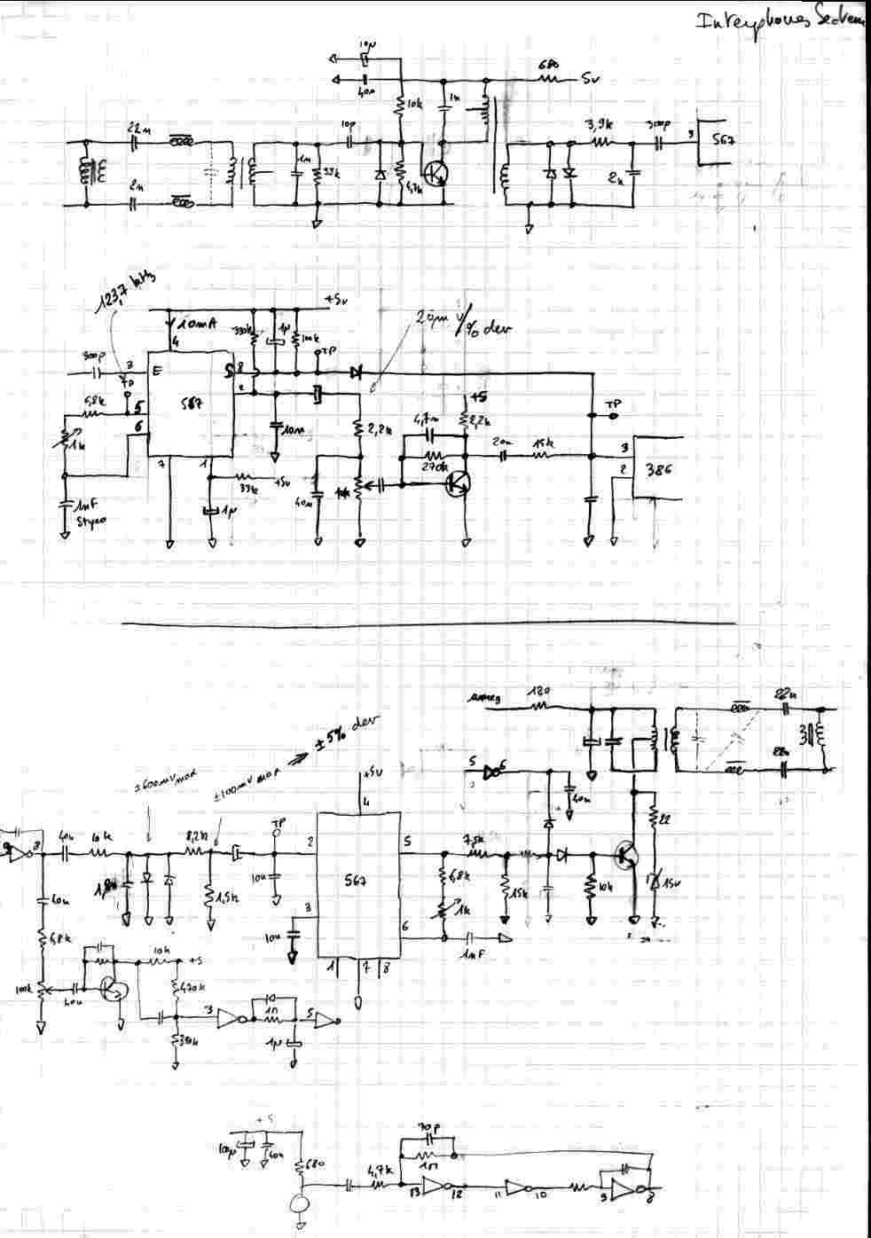
Les bandes B et D sont utilisables sans protocole comme par exemple, des interphones (babyphone). Voir ici le schéma d'un interphone secteur analogique à 123 kHz, utilisant des PLL NE567.
Le bus X10 utilise la bande B.
Le protocole est obligatoire dans la bande C (CSMA/CA carrier sense multiple access with collision avoidance), les circuits modem courants sont les TDA5051 (digital 1200 bauds, Philips) et ST7537 (analogique 2400 bauds, STM), toujours centrés sur 132.5 kHz.
Les hauts débits
 Pour les hauts
débits, la bande supérieure va être utilisée :
Pour les hauts
débits, la bande supérieure va être utilisée :
Le groupe de travail CENELEC SC205A n’a pas encore finalisé la norme, l’ETSI y travaille aussi, l’Allemagne (NB30 RegTP NutzungBestimmung) et le royaume uni ont défini des dispositions propres.
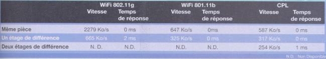
Un seul standard mondial : HomePlug (version 1.0.1) créé par « HomePlug PowerLine Alliance » (EDF, France Telecom, Motorola, Netgear…) Indoor uniquement. voir le site http://www.homeplug.org. Le principe est une modulation multi-fréquentielle (ODFM), et le débit physique peut monter jusqu’à 14Mbps, le débit réel ne dépasse pas 5Mbps et tombe vite avec la distance, comme le montre cet article de la revue Hardware magazine (dec/janvier 2004), ou encore cette analyse sur le site de m@tbe.com
Une version High Speed (1.1) est disponible avec un débit théorique de 85Mbps (15Mbps en pratique), voir le test d'un coupleur CPL HS sur le site www.cpl-france.com
L'évolution de la norme HomePlug vers HomePlug AV (200 Mbps) est normée, elle est totalement incompatible avec les versions 1.01 et 1.1 mais les 2 protocoles peuvent cohabiter.
Le bus X-10 voir aussi :
http://www.si.ens-cachan.fr/ressource/r5/r5_X10.htm
http://www.cix.co.uk/~pplunkett/x10.htm un récepteur perso à base de PIC
http://www.geocities.com/ido_bartana/ le site référence X10
copié du site www.x10.com ; résumé -----------------------------------------------------------------------------
X10 utilise une transmission au passage à zéro +/- 200 usec max, puis à 3.33ms puis à 6.33ms
F0 = 120 kHz
1 = 1 burst de 1ms de 120kHz
0 = absence
chaque bit est répété 2 fois (b et /b)
chaque message est répété 2 fois, sans période de silence en les 2
la séquence minimale fait 220 msec + 60 msec de silence
| N° de zéro cross |
bit |
mot |
| 0 |
1 |
mot de synchro 2 bits, =10 |
| 1 |
1 |
|
| 2 |
1 |
|
| 3 |
0 |
|
| 4 |
a0 |
mot d'adresse sur 4 bits, lsb first |
| 5 |
/a0 |
|
| 6 |
a1 |
|
| 7 |
/a1 |
|
| 8 |
a2 |
|
| 9 |
/a2 |
|
| 10 |
a3 |
|
| 11 |
/a3 |
|
| 12 |
d0 |
mot de donnée sur 5 bits, lsb first |
| 13 |
/d0 |
|
| 14 |
d1 |
|
| .... |
||
| 20 |
d4 |
|
| 21 |
/d4 |
|
| silence = 3 bits à zéro au moins = 60msec |
||
C'est plutôt lent (1/2 seconde pour 1 ordre) et bien fait pour des commandes d'éclairage, des stores, de vannes
Pas du tout adapté à de l'acquisition de données
----------------------------------------------------------------------------------------------------------------------
X-10 communicates between transmitters and receivers by sending a receiving signals over the power line wiring. These signals involve short RF bursts which represent digital information.
X-10 transmissions are synchronized to the zero crossing
point of the AC power line. The goal should be to transmit as close to the
zero crossing point as possible, but certainly within 200 microseconds of
the zero crossing point. The PL513 and TW523 provide a 60 Hz square wave with
a maximum delay of 100 µsec from the zero crossing point of the AC power line.
The maximum delay between signal envelope input and 120 kHz output bursts
is 50 µsec. Therefore, it should be arranged that outputs to the PL513 and
TW523 be within 50 µs of this 60 Hz zero crossing reference square wave.
.
.
A Binary 1 is represented by a 1 millisecond burst of 120 kHz at the zero crossing point, and a Binary 0 by the absence of 120 kHz. The PL513 and TW523 modulate their inputs (from the O.E.M.) with 120 kHz, therefore only the 1 ms "envelope" need be applied to their inputs. These 1 millisecond bursts should equally be transmitted three times to coincide with the zero crossing point of all three phases in a three phase distribution system. Figure 1 shows the timing relationship of these bursts relative to zero crossing.
.
 .
.
.
A complete code transmission encompasses eleven cycles of
the power line. The first two cycles represent a Start Code. The next four
cycles represent the House Code and the last five cycles represent either
the Number Code (1 thru 16) or a Function Code (On, Off, etc.). This complete
block, (Start Code, House Code, Key Code) should always be transmitted in
groups of 2 with 3 power line cycles between each group of 2 codes. Bright
and dim are exceptions to this rule and should be transmitted continuously
(at least twice) with no gaps between codes. See Figure 2.
.
.
Within each block of data, each four or five bit code should be transmitted in true compliment form on alternate half cycles of the power line. I.E. if a 1 millisecond burst of signal is transmitted on one half cycle (binary 1) then no signal should be transmitted on the next cycle, (binary 0). See Figure 3.
The Tables in Figure 4 show the binary codes to be transmitted
for each House Code and Key Code. The Start Code is always 1110 which is a
unique code and is the only code which does not follow the true complimentary
relationship on alternate half cycles.
.
.
[1] Hail Request is transmitted to see if there are any X-10 transmitters within listening range. This allows the O.E.M. to assign a different Housecode if a "Hail Acknowledge" is received.
[2] In a Pre-Set Dim instruction, the D8 bit represents the Most Significant Bit of the level and H1, H2, H4 and H8 bits represent the Least Significant Bits.
[3] The Extended Data code is followed by 8 bit bytes which can represent Analog Data (after A to D conversion). There should be no gaps between the Extended Data code and the actual data, and no gaps between data bytes. The first 8 bit byte can be used to say how many bytes of data will follow. If gaps are left between data bytes, these codes could be received by X-10 modules causing erroneous operation.
Extended Code is similar to Extended Data: 8 Bit bytes which follow Extended Code (with no gaps) can represent additional codes. This allows the designer to expand beyond the 256 codes presently available.
NOTE 1. X-10 Receiver Modules require a "silence" of at least 3 power cycles between each pair of 11 bit code transmissions (no gaps between each pair). The one exception to this rule is bright and dim codes. These are transmitted continuously with no gaps between each 11 bit dim code or 11 bit bright code. A 3 cycle gap is necessary between different codes, i.e. between bright and dim, or 1 and dim, or on and bright, etc.
NOTE 2. The TW523 Two-Way Power Line Interface cannot receive Extended Code or Extended Data because these codes have no gaps between them. The TW523 can only receive standard "pairs" of 11 bit X-10 codes with 3 power line cycle gaps between each pair.
NOTE 3. The TW523 can receive dim and bright codes but the output will represent the first dim or bright code received, followed by every third code received. i.e. the output from the TW523 will not be a continuous stream of dim and bright codes like the codes which are transmitted.
A Square wave representing zero crossing detect is provided by the PL513/TW523 and is within 100 µs of the zero crossing point of the AC power line. The output signal envelope from the O.E.M. should be within 50 µs of this zero crossing detect. The signal envelope should be 1 ms (-50µs +100µs). See Figure 5.
Opto-Coupled 60 Hz reference output (from the PL513/TW523)
Transmissions are to be synchronized to the zero crossing point of the AC power line and should be as close to true zero crossing as possible. The PL513 and TW523 are designed to be interfaced to other microprocessor circuitry which outputs X-10 codes synchronized to the zero crossing point of the AC power line. It is therefore necessary to provide a zero crossing reference for the O.E.M. microprocessor.
It is likely that this microprocessor will have its own "isolated" power supply. It is necessary to maintain this isolation, therefore the trigger circuit normally used in X-10 POWERHOUSE controllers is not desirable as this would reference the O.E.M. power supply to the AC power line. It is also not desirable to take the trigger from the secondary side of the power supply transformer as some phase shift is likely to occur. It is therefore necessary to provide an opto-coupled 60 Hz reference.
An opto-coupled 60 Hz square wave is provided at the output of the PL513 and TW523. X-10 codes generated by the O.E.M. product are to be synchronized to this zero crossing reference. The X-10 code envelope generated by the O.E.M. is applied to the PL513 or TW523 which modulates the envelope with 120 kHz and capacitively couples it to the AC power line.
Opto-Coupled Signal Input (to the PL513/TW523)
The input signal required from the O.E.M. product is the signal "envelope" of the X-10 code format, i.e.
High for 1 ms. coincident with zero crossing represents a binary "1" and gates the 120 kHz oscillator through to the output drive circuit thus transmitting 120 kHz onto the AC power line for 1 ms.
Low for 1 ms. coincident with the zero crossing point represents a binary "0" and turns the 120 kHz oscillator/output circuit off for the duration of the 1 ms. input.
.
.
Opto-Coupled Signal Output (from the TW523)
The "X-10 received" output from the TW523 coincides with the second half of each X-10 transmission. This output is the envelope of the bursts of 120 kHz received. Only the envelope corresponding to the first burst of each group of 3 bursts is available at the output of the TW523. See Figures 6, 7 and 8.
.
.